Abstract
Cutting down CO2 emissions from blast furnace (BF) ironmaking is a critical area of research. Utilization of hydrogen as a reducing agent has been regarded as one of the most promising solutions to address this challenge. This study examined the impact of using hydrogen injection on the isothermal reduction of commercial iron ore pellets under conditions simulating the center and wall areas of a BF. The effect of distinct reducing conditions, influenced by the radial position within a BF and the amount of hydrogen injected, on the reducibility, swelling, cracking, and porosity of pellets was investigated. A high-temperature furnace with a thermogravimetric analyzer was utilized to simulate the atmospheres of CO–CO2–H2–H2O–N2 at 700, 900 and 1100°C in 300-minute experiments. The changes in volume and porosity of the pellets were determined based on the results obtained using a gas pycnometer and manual measurement. The phase transformations were studied using microscopy and X-ray diffraction. The results show that the addition of hydrogen had an accelerating effect on the reduction rates excluding the experiment conducted at 700°C under center conditions of a BF, during which the high level of water vapor led to oxidation of the pellet on the surface rather than reduction at the beginning of the wüstite–metallic iron reduction stage. Furthermore, the pellets swelled less in hydrogen-enriched atmospheres. Also, it should be highlighted that the reduction was significantly faster near the center of a BF compared to the areas near the walls.
1. Introduction
In the coming decades, steel and iron industries must undergo massive changes from conventional fossil carbon-based production methods towards fossil-free solutions due to the European Union’s striving for a 55% decrease of CO2 emissions by 2030 (compared to 1990 levels) and carbon neutrality by 2050.1) Moreover, 130 countries around the globe have established climate goals, and China, the world’s largest producer of steel, also aims to become carbon neutral by 2060.2) Based on the latest report by World Steel Association,3) the production route through blast furnaces (BF) is still by far the most common ironmaking method. Globally, it accounts for 71.1% of total production and generates CO2 emissions at an average of 2330 kg per tonne of hot metal (tHM). Hydrogen is a promising reducing agent to replace fossil coal and coke in ironmaking. As a result of the reduction reaction with hydrogen gas, water is formed instead of CO2. Over the past few years, the growing interest in hydrogen-based reduction of iron ore has been reflected in the increased number of review articles.4,5,6,7,8,9,10) One of the main challenges is the limited availability of renewable hydrogen, which restricts the transition to entirely hydrogen-based fossil-free steel via direct reduced iron (DRI). Given the substantial number of operational BFs, it is crucial to evaluate emission reduction strategies through their conversion to hydrogen-assisted processes. Also, it is vital to understand the characteristics of current processes to develop future iron and steelmaking methods.11)
In BF processes, hydrogen can be utilized as a reducing gas instead of CO by injecting it to the furnace via tuyères or shaft, improving energy efficiency. In this study, pure hydrogen injection is investigated. However, injecting hydrogen-abundant materials such as coke oven gas (COG), natural gas (NG) and heavy oil into BFs is already rather common in large, industrialized countries.6,7) In addition, there is potential to utilize synthetic gases. COG can be very hydrogen-rich: Perret et al.12) reported the hydrogen content of 63 vol-%. Utilization of NG is possible using tuyère injection or prereduction of iron ore.13) Injection of pure hydrogen or hydrogen-abundant gases can be combined with the use of DRI, hot briquetted iron (HBI) and top gas recycling to decrease the amount of coke needed to operate the processes. Nonetheless, the endothermic nature of indirect reduction with hydrogen limits the amount of hydrogen gas to be utilized in the reducing atmosphere. In BFs, hydrogenous gas injection intensifies the water gas shift reaction, which has a direct effect on how CO and H2 are utilized in the top gas.14) The optimum hydrogen enrichment must be based on the minimum amount of coke which is consumed to maintain permeability and generate the heat needed for furnace operation.4) It has been reported that part of coke and pulverized coal injection (PCI) can be replaced by H2, but further research is needed to identify the maximum possible injection level.15) Also, further experimental work is required to better understand the water gas shift reaction with larger H2 injection rates.16,17)
The potential for utilizing higher hydrogen enrichment levels in actual BFs depends on operating conditions and is presently derived from simulations. Based on modeling, Yilmaz et al.18) estimated that under optimal operation conditions, a decrease of 21.4% in CO2 emissions is possible with an H2 injection rate of 27.5 kg/tHM and a PCI rate of 120 kg/tHM. Yu et al.19) concluded that fossil fuel savings of 28 kg/tHM can be expected with an H2 shaft injection rate of 30 m3/h. Modeling by Okosun et al.20) predicted that stable operation of a BF is possible with H2 injection up to 30 kg/tHM, and that 25 kg/tHM of injected H2 would result in a decrease of 60 kg/tHM in coke consumption. Nonetheless, these results do not yet allow for a conclusion to be drawn regarding the actual decrease of CO2 emissions. It can be roughly estimated that the potential for cutting CO2 emissions by pure hydrogen injection via tuyères is 25–35%. On the other hand, according to Nippon Steel, using heated hydrogen H2 injection could result in more significant decreases in emissions: in their test furnace, a decrease of 43% in CO2 emissions was achieved.21)
To date, according to the announcements from various steel companies, several successful pure hydrogen injection trials in actual BFs have been performed globally. The first industrial BF trial was carried out by Thyssenkrupp in Duisburg, Germany in 2019.22) Tata Steel performed an H2 trial in Jamshedpur, India in 2023.23) Cliffs has accomplished two trials in the United States: the first in Middletown in 2023 and the second in Indiana Harbor in 2024.24) The latest H2 trial was carried out by Erdemir in Istanbul, Turkey in 2024.25) Based on the reported values, the injection rates mainly varied between 0.6–3.9 kg/tHM in BFs with capacities ranging from 0.36 to 3.5 million tons per annum. Tata Steel states that achieving a 10% decrease in the coke rate leads to a lowering of 7–10% in CO2 emissions per tHM.23)
Along with sinter, iron ore pellets are the main ferrous charge material in BF ironmaking. This work focused on investigating the reduction behavior of commercial iron ore pellets in H2-enriched atmosphere before the melting conditions in the cohesive zone of the BF at the temperatures of 700–1100°C. The phenomena taking place in BF are exceedingly complex. Even when accounting for the reactions occurring within the cohesive zone, it is important to note that the conditions at the center of the furnace differ from those near the walls. Coke is mainly charged from the center, which increases the concentration of CO gas in the central zone of the furnace. Moving from the center towards the periphery of the furnace, CO levels decrease. At the same time, temperatures decrease due to the cooling system close to the walls.26)
Pellets have unique metallurgical properties, of which reducibility, porosity, swelling and cracking were studied in this work. Pellet reducibility can be studied by evaluating phase transformations occurring in samples during reduction reactions. Reduction takes place from hematite (Fe2O3) to magnetite (Fe3O4), then wüstite (FeO) and further to metallic iron (Fe). The porosity of the ferrous material is known as a factor that favorably affects the reaction kinetics during reduction. That is, porosity tends to increase as reduction occurs, expanding the reaction area of pellets.27) In the present study, pellet porosity is investigated before and after reduction in different gas atmospheres following calculated conditions in BF center and wall areas. Pellets tend to swell during reduction, and sometimes it results in cracking, which can also lead to pellet disintegration. Avoiding this undesirable phenomenon by examining the cold compressive strength of pellets was investigated in the previous study.28)
Researchers have reported that increasing the H2 content of BF gas improves the reduction kinetics of iron ore pellets.29,30) Many studies on the reduction of pellets employing H2 have also been conducted in the laboratory of Process Metallurgy at the University of Oulu.31,32,33,34,35) As reported by Heidari et al.,31) reduction using H2 is remarkably faster than with CO for both BF and DRI pellets. Atmospheres of CO–CO2–H2–H2O–N2 have also been simulated using a layer furnace34) and a blast furnace gas phase simulator.33,35) It has been demonstrated that even a small addition of H2 (4–7 vol.-% ) positively influences the progress of reduction. Additionally, the reduction occurred more rapidly under conditions simulating the center area of a BF compared to the area near the walls. According to the recently conducted experimental research on the effect of H2 injection on the reducibility of pellets36) as well as degradation of pellets, sinter and lump,37) using H2 in reducing atmosphere affects the formation of cracks and the reduction rate at lower temperatures.
The goal of this study was to collect and analyze valuable data on the behavior of commercial iron ore pellets in conventional and H2-enriched blast furnace conditions. This further helps to deepen the technical understanding of implementation of H2 injection as a part of cutting down CO2 emissions in the iron and steel industry. The phase transformations occurring during reduction were initially assessed based on weight loss during experiments, after which they were studied using microscopy and X-ray diffraction (XRD).
2. Materials and Methods
2.1. Iron Ore Pellets and Reduction Degree
In the experimental part of this work, commercial iron ore pellets were used to study reduction in distinct gas atmospheres. The pellets were acid with basicity B2 of 0.20 (the ratio of CaO and SiO2). Table 1 presents the chemical composition delivered by the pellet supplier.
Table 1. Chemical analysis (wt-%) of the iron ore pellets studied.
| Fetot | FeO | Mn | P | SiO2 | Al2O3 | CaO | TiO2 | MgO | Basicity B2 (CaO/SiO2) |
|---|
| 66.62 | 0.30 | 0.04 | 0.02 | 2.68 | 0.34 | 0.54 | 0.19 | 0.57 | 0.20 |
Due to a broad particle size distribution, the pellets were sieved prior to reduction experiments. The diameter of pellets mainly varied between 8 and 16 mm. Because it was possible to use only one pellet in each experiment due to the capacity of the experimental apparatus, large pellets with a particle size of approximately 13 mm were selected to maximize the sample size. Pellets as round as possible were chosen for the experiments to minimize the inaccuracy of volume measurements. The pellets were dried overnight in a ventilated oven at 105°C to avoid moisture adsorption from the air. The weight of each dried pellet was 4.3 ± 0.1 g prior to experiment. Based on the chemical composition and the change in weight during reduction, reduction degrees for the pellet samples were calculated using Eq. (1) based on ISO 7215.38)
|
RD=[
Δm
m
0
(
0.430
w
2
-0.111
w
1
)
×100
]×100%
| (1) |
where RD is the reduction degree (%), m0 is the decrease in weight of the pellet during the reduction (g), w1 is the iron (II) oxide content (wt-%) of the pellet prior to the test, and w2 is the total iron content (wt-%) of the pellet prior to the test.
2.2. Measurement of Density and Porosity
Morphological changes during reduction were studied by assessing the changes in pellet volume by calculating the reduction–swelling index (RSI) and pellet porosity before and after the experiments. Fig. 1 shows how diameters of the pellets were measured manually from nine directions using a digital slide gauge. The average of nine measurements was used as the final pellet diameter value.

Fig. 1. Manual pellet diameter measurement in nine directions with two rotations. (Online version in color.)
The reduction–swelling index (RSI) can be calculated based on pellet diameters as follows:
|
RSI=[
(
d
1
d
0
)
3
-1
]×100%
| (2) |
where d0 is the diameter of the pellet before reduction (mm) and d1 is the diameter of the pellet after reduction (mm).
To determine the porosity of pellets, it is necessary to know the density. Envelope density (ρe), which does not consider pores or cracks in the pellet, was calculated for each original and reduced pellet as follows:
where ρe is the envelope density of the pellet (g/cm3), m is the mass of the pellet (g), and V is the volume of the pellet (cm3) based on the manually measured diameter.
Micromeritics Accupyc II 1340 gas displacement pycnometer enabled the measurement of the porosity of the pellets. In the analyzes, which were performed five times for each sample, helium gas was introduced into the 10 cm3 chamber of the pycnometer. The gas penetrated the open pores of the pellet, allowing the measurement of the skeletal density (ρs). Pellet porosity (ε) for the original and reduced pellets was further determined as follows:
2.3. Reduction Experiments
Conditions for wall and center positions simulated in this work were based on stable BF conditions studied using the MOGADOR (Model of Gas Distribution and Ore Reduction)39) model with descending burden and fixed profiles of temperature and gas composition. The two gas profiles varied based on the volume of hydrogen injected. The base case model served as a reference point when researching the influence that adding hydrogen has on reduction. The modeling was based on the operation of the largest blast furnace (BF7) located at the Tata Steel IJmuiden site in the Netherlands, observed from 19 to 21 May 2023. Plant data including the above burden temperature, the top gas temperature, the gas utilization, and the pressure along the heights were utilized in the validation of the model. The main operational parameters are shown in Table 2.
Table 2. The type of fuel and the ratios of pulverized coal injection (PCI) and coke in simulated hydrogen injection scenarios.
| Hydrogen injection ratio | 0 kg/tHM | 20 kg/tHM |
|---|
| Type of injected fuel | PCI | PCI + H2 |
| PCI ratio (kg/tHM) | 229 | 229 |
| Coke ratio (kg/tHM) | 296 | 261 |
A total of 12 isothermal reduction programs were created to perform experiments at temperatures of 700, 900 and 1100°C. For this paper, the experiments were named according to the three aforementioned factors as shown in Table 3: W stands for wall conditions, C for center conditions, BC for base case gas profile, H2 for increased hydrogen injection, and the two last digits for the temperature in hundreds of °C. The atmospheres for the reduction stages of the experiments are listed in Table 4. Fe–O–C and Fe–O–H phase stability diagrams presented in Fig. 2 show the gas utilization in the original dynamic scenarios and the state of each isothermal experiment carried out in the present study.
Table 3. The isothermal experiments with two radial positions, two reducing gas atmospheres and three different temperatures.
| Experiment | Radial Position | Gas Profile | Temperature (°C) |
|---|
| Wall | Center | Base Case | 20 kg H2/tHM |
|---|
| WBC-07 | X | | X | | 700 |
| WH2-07 | X | | | X | 700 |
| CBC-07 | | X | X | | 700 |
| CH2-07 | | X | | X | 700 |
| WBC-09 | X | | X | | 900 |
| WH2-09 | X | | | X | 900 |
| CBC-09 | | X | X | | 900 |
| CH2-09 | | X | | X | 900 |
| WBC-11 | X | | X | | 1100 |
| WH2-11 | X | | | X | 1100 |
| CBC-11 | | X | X | | 1100 |
| CH2-11 | | X | | X | 1100 |
Table 4. The gas compositions of the reduction experiments.
| Experiment | CO (vol-%) | CO2 (vol-%) | H2 (vol-%) | H2O (vol-%) | N2 (vol-%) |
|---|
| WBC-07 | 29.32 | 22.71 | 6.31 | 5.98 | 35.68 |
| WH2-07 | 27.09 | 19.16 | 15.30 | 11.79 | 26.67 |
| CBC-07 | 36.72 | 13.86 | 8.45 | 3.80 | 37.16 |
| CH2-07 | 34.61 | 12.72 | 18.12 | 8.65 | 25.90 |
| WBC-09 | 40.83 | 11.68 | 8.86 | 3.30 | 35.32 |
| WH2-09 | 35.28 | 11.36 | 18.88 | 7.99 | 26.49 |
| CBC-09 | 43.38 | 6.40 | 10.22 | 1.97 | 38.03 |
| CH2-09 | 40.54 | 6.04 | 22.12 | 4.30 | 27.00 |
| WBC-11 | 46.17 | 4.71 | 10.31 | 2.27 | 36.54 |
| WH2-11 | 40.81 | 4.18 | 22.87 | 4.85 | 27.30 |
| CBC-11 | 47.82 | 0.74 | 12.15 | 0.42 | 38.86 |
| CH2-11 | 43.93 | 1.40 | 25.30 | 1.71 | 27.67 |

Fig. 2. Bauer-Glaessner diagrams of the utilization of (a) CO and (b) H2 gases in the reduction experiments.
The experiments were carried out under laboratory conditions using a tailor-made high-temperature furnace with a thermogravimetric analyzer (TGA). The furnace included a vertical reduction tube with an inner diameter of 31.5 mm, inside which the sample basket connected to the scale for TGA was lowered. The lower part of the furnace, the hotspot, was computer-aided: the temperature, gas composition and gas flow rate were able to be adjusted at any time or a predefined program could be used. Multiple gases were available enabling the creation of variable gas atmospheres. To achieve reducing conditions, H2, CO, CO2 and N2 gases were utilized in this work. The gases were fed into the hotspot at a flow rate of 2 l/min (at NTP conditions). In addition, water vapor was used in the experiments by feeding water into the furnace with the help of a peristaltic water pump calibrated before each experiment. The experimental setup is depicted in Fig. 3.

Fig. 3. Principle of the high-temperature TGA apparatus used in the reduction experiments. (Online version in color.)
Two replicates were carried out for one program (WBC-11) to ensure reproducibility of the trials. Each experiment followed the gas atmosphere of CO–CO2–H2–H2O–N2 determined for the program. Initially, the furnace was preheated to the target temperature. Each program began with a 10-minute nitrogen purging. This was followed by an isothermal reduction stage of 300 minutes. Next, in experiments using temperatures above 700°C, the samples were cooled down to 700°C in the hotspot using N2 gas. After the temperature dropped below 700°C, the basket with the sample was elevated into the cooling chamber, in which it was allowed to cool to room temperature for 10 minutes using N2 gas injection and cooling water circulation.
2.4. Mineralogical Characterizations
To study phase transformations, polished sections were made of an original pellet and the pellet samples exposed to all 12 reduction experiments. A digital Olympus DSX1000 light optical microscope (LOM) and a Zeiss ULTRA Plus field emission scanning electron microscope (FESEM; complete with an energy-dispersive X-ray spectroscopy (EDS) elemental analyzer manufactured by Oxford Instruments) were used in investigating the cross-section areas of the pellets. The samples were carbon-coated for FESEM-EDS analyses, which utilized backscattering and 15 kV imaging resolution.
Phase identifications for an original pellet and each reduced pellet were performed using a Rigaku SmartLab 9 kW X-ray diffraction system (XRD). Each pellet sample was ground to a fine powder using a Retsch MM400 mixer mill prior to XRD measurements.
3. Results and Discussion
3.1. Reduction
The replicates performed on program WBC-11 were compared by calculating the relative standard deviation (RSD) of the reduction degree during the experiments and expressing them as a function of time. The results depicted in Fig. 4 show that five minutes after the start of the experiment, the RSD settled at approximately 5%, decreasing towards the end of the experiment. Based on this, the reproducibility of the experiments can be considered good. The reduction curve of experiment WBC-11 discussed in this work was added to the graph to illustrate the progress of the experiment.

Fig. 4. Relative standard deviation (RSD) of the reduction degree of the three runs using the program of experiment WBC-11, and the reduction curve for the single experiment (WBC-11) discussed in this work.
Reduction degrees obtained for the pellets in BF wall and center conditions are presented in Fig. 5 as a function of time with boundaries for magnetite-wüstite and wüstite-metallic iron transformations considering the nonstoichiometry of wüstite. Based on the measurements by TGA, using base case gas atmosphere under wall conditions at the temperatures of 700, 900 and 1100°C, final reduction degrees of 24.9%, 85.4% and 98.6% were obtained for experiments WBC-07, WBC-09 and WBC-11, respectively. The corresponding results in H2-enriched experiments WH2-07, WH2-09 and WH2-11 were 27.8%, 91.2% and 97.5%. Using base case gas atmosphere under center conditions at 700, 900 and 1100°C, reduction degrees of 42.4%, 98.1% and 99.1% were obtained for experiments CBC-07, CBC-09 and CBC-11. Respectively, the results with elevated H2 injection in experiments CH2-07, CH2-09 and CH2-11 were 30.6%, 98.5% and 100.2%. The pellets were therefore completely or almost completely reduced to metallic iron in all experiments performed at 1100 and 900°C. In experiments carried out under wall conditions at 700°C, the reduction slowed down considerably at the magnetite–wüstite step with both gas compositions and under center conditions for the H2-enriched atmosphere.

Fig. 5. Reduction degrees of pellets for experiments performed using base case and H2-enriched gas profiles under (a) wall conditions and (b) center conditions.
As can be seen from the reduction curves, the reduction rate during the reduction step from hematite to magnetite was higher in all scenarios with H2-enriched atmosphere. In addition, the reduction steps from magnetite to wüstite and further to metallic iron were also faster with the elevated H2 gas profile, except for the experiment performed at 700°C under center conditions. After 80 minutes of reduction, the reduction degree of the pellet in experiment CBC-07 exceeded that of CH2-07. Reduction to wüstite had occurred after 90 minutes in experiment CBC-07, after which the reduction reactions continued at a steady rate towards metallic iron. In the case of CH2-07, the reduction rate slowed down significantly suggesting that only a little amount of metallic iron was formed during the 300-minute experiment.
From the perspective of the reduction rate and the final reduction degree, results were therefore favorable for higher hydrogen and water vapor utilization at higher temperatures. Under center conditions at 700°C, according to the stability diagram, the reducing conditions were in the wüstite range for both gas compositions, but in the H2-enriched atmosphere, the final RD was considerably lower. Such a difference between gas compositions was not observed under wall conditions that were more favorable for the H2-enriched atmosphere, although the results of both low-temperature experiments (WBC-07 and WH2-07) remained at the magnetite–wüstite reduction stage.
3.2. Porosity Change, Swelling and Cracking
The results for reduction degree, reduction-swelling index, density and porosity are compiled in Table 5. The calculated density and porosity values are presented for both original and reduced pellets. The porosity values measured for the reduced pellets after each experiment are presented together with the original pellet average porosity as a function of reduction degree in Fig. 6. The results for swelling are shown in Fig. 7.
Table 5. Results for reduction degree (RD), reduction-swelling index (RSI), envelope density, skeletal density, and porosity calculations for each pellet sample.
| Exp. | RD (%) | RSI (%) | Original pellet | Reduced pellet |
|---|
| Envelope density (g/cm3) | Skeletal density (g/cm3) | Porosity (%) | Envelope density (g/cm3) | Skeletal density (g/cm3) | Porosity (%) |
|---|
| WBC‑07 | 24.9 | 4.8 | 3.686 | 5.294 | 30.4 | 3.268 | 5.647 | 42.1 |
| WH2‑07 | 27.8 | 5.6 | 3.722 | 5.353 | 30.5 | 3.244 | 5.790 | 44.0 |
| CBC-07 | 42.4 | 0.7 | 3.569 | 5.277 | 32.4 | 3.114 | 6.030 | 48.4 |
| CH2-07 | 30.6 | 2.1 | 3.664 | 5.299 | 30.9 | 3.273 | 5.818 | 43.7 |
| WBC‑09 | 85.4 | 11.7 | 3.865 | 5.390 | 28.3 | 2.615 | 7.296 | 64.2 |
| WH2‑09 | 91.2 | 5.5 | 3.567 | 5.412 | 34.1 | 2.498 | 7.472 | 66.6 |
| CBC-09 | 98.1 | 13.9 | 3.719 | 5.367 | 30.7 | 2.348 | 8.045 | 70.8 |
| CH2-09 | 98.5 | 9.7 | 3.798 | 5.393 | 29.6 | 2.486 | 7.826 | 68.2 |
| WBC-11 | 98.6 | 43.8 | 3.648 | 5.399 | 32.4 | 1.822 | 7.749 | 76.5 |
| WH2-11 | 97.5 | 32.0 | 3.790 | 5.349 | 29.2 | 2.071 | 7.803 | 73.5 |
| CBC-11 | 99.1 | 50.9 | 3.703 | 5.352 | 28.7 | 1.758 | 7.665 | 77.1 |
| CH2-11 | 100.2 | 30.3 | 3.736 | 5.383 | 30.6 | 2.045 | 7.847 | 73.9 |
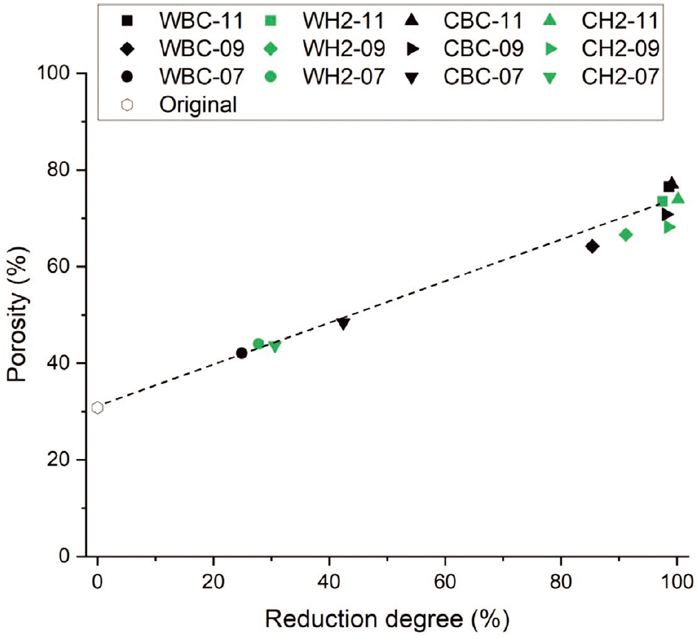
Fig. 6. Average porosity (%) of the original pellet samples and the porosities of the reduced pellet samples after each reduction experiment.

Fig. 7. Calculated swelling (%) for the pellets after each reduction experiment under (a) wall and (b) center conditions.
Porosity increased almost linearly with reduction degree, and compared to the original pellet, more than doubled when the metallic iron reduction stage was reached. The porosity of the original pellets was approximately 30%, from which it increased to 40–50% during the magnetite–wüstite reduction step and finally to over 70% for the completely reduced pellets. This applies to all experiments. For the experiments conducted at 700°C, porosity was clearly higher in the pellet with the highest reduction degree, i.e., the pellet subjected to experiment CBC-07. Except for this, there were no significant differences between the two gas atmospheres in the temperatures studied. However, previous experimental simulation work33) showed that the use of H2 injection increases pellet porosity during reduction compared to a scenario where only CO, CO2 and N2 are utilized.
Based on RSI calculations, swelling was strongest in experiments performed at 1100°C, although there were clear differences between them. In the base case atmosphere, pellets tended to swell more, up to about 50%, compared to H2-enriched atmosphere, where the swelling remained at about 30%. According to the results of the reduction experiments carried out by Yi et al.,40) the formation of the wüstite phase expands the pellet structure, but in H2-enriched atmosphere, this effect is weakened due to the rapid passing of the wüstite reduction stage. Swelling also appeared to be stronger under wall conditions than under center conditions. Swelling was minor, less than 15%, in tests conducted at lower temperatures. Pellets with low B2 basicity, such as the pellets studied here, do not tend to swell remarkably upon reduction.26)
In addition, as Fig. 8 shows, cracking was detected among the reduced test pellets. Only minor cracking was observed with the pellets reduced at 700 and 900°C. Cracking is usually strongest at temperatures above 1000°C since it is connected to high reducibility and swelling. Although the pellets were completely reduced at 900°C under center conditions, they nevertheless did not crack as strongly as the pellets reduced at 1100°C. This is attributed to the growth of iron ore whiskers resulting from a high reduction rate.41) Cracking was of the same magnitude in both gas atmospheres.

Fig. 8. All 12 test pellet samples pictured before and after the reduction experiments.
The cracking occurred in the pellets also affected their diameter, which was reflected in the swelling results. The phenomenon also influenced the porosity determinations made on reduced pellets, because in the method used, helium penetrates the cracks in the pellet.
3.3. XRD Observations
The main mineralogical phases present in the pellets were analyzed using XRD. The analysis for the original pellet depicted in Fig. 9 shows that the predominant phase in the original pellet was hematite and nothing suggestive of a magnetite core was found. The XRD analysis was performed on one original pellet sample. Therefore, it is not known whether magnetite could have been present in some of the pellets in the batch. The analysis results for pellet samples reduced in wall and center conditions are presented in Fig. 10.

Fig. 9. XRD analysis results of an original unreduced pellet sample.
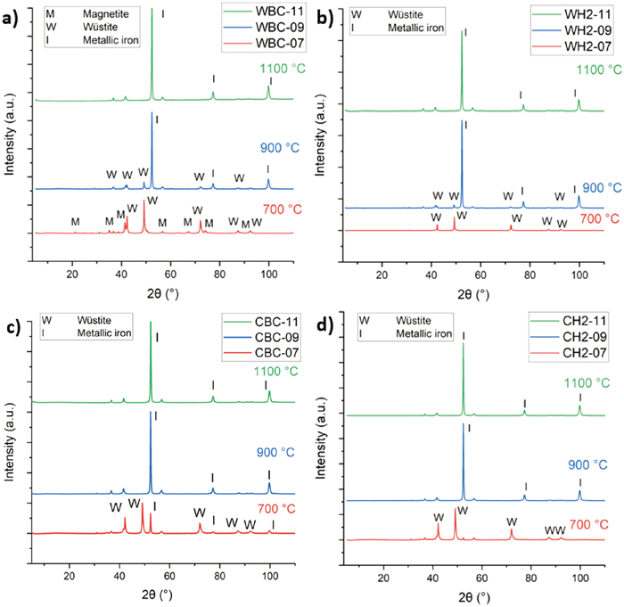
Fig. 10. XRD results for iron ore pellets reduced under (a) wall conditions using base case atmosphere (b) wall conditions using H2-enriched atmosphere (c) center conditions using base case atmosphere and (d) center conditions using H2-enriched atmosphere.
According to XRD analysis shown in Fig. 10(a), traces of magnetite among wüstite were detected in the pellet subjected to experiment WBC-07. As can be seen from Fig. 10(b), no similar result was observed in the case of experiment WH2-07 as only peaks for wüstite were detected. For WBC-09 and WH2-09, mainly metallic iron and minor wüstite phases were found. For the pellets reduced at 1100°C under wall conditions, only phases with metallic iron were observed. This also appeared to be true under center conditions, but the results were similar at 900°C as well. A notable observation is that, as depicted in Fig. 10(c), metallic iron phases were present in the pellet after experiment CBC-07, alongside wüstite. However, metallic iron was not detected in the case of experiment CH2-07, as shown in Fig. 10(d).
3.4. Microscope Images
The phase transformations based on TG curves and observations using LOM were confirmed using FESEM-EDS. In addition, a polished section of the original pellet was studied. A FESEM image shown in Fig. 11 reveals that the original pellet contained some minor phases identified by EDS: quartz (SiO2) and olivine ((Mg,Fe)2SiO4) as a source of MgO.

Fig. 11. FESEM image of the original pellet sample with olivine, quartz and oxidic iron phases in the periphery area.
As can be detected from the LOM images shown in Fig. 12 reduction under wall conditions at 700°C has progressed to the wüstite stage, but no further, as there is no metallic iron visible in the core or periphery areas of the pellet. There are no noticeable differences between the images taken from the pellets reduced in the base case and H2-enriched gas atmospheres.

Fig. 12. LOM images taken from the core and periphery areas of the pellets reduced under wall conditions at 700°C, i.e., after experiments WBC-07 and WH2-07 whose reduction degree (RD) results are marked in the image. (Online version in color.)
However, as can be seen from the LOM images presented in Fig. 13, for the experiments performed at 700°C under center conditions, the corresponding images of the two gas profiles look different. For the base case gas profile, metallic iron visible as white dots is observed in larger areas in the periphery, but only in small amounts in the core. Typically, reduction proceeds in this way from the pellet surface to the core. Nevertheless, in the H2-enriched gas profile, metallic iron is hardly detected at the periphery areas, and the amount of metallic iron formed in the core appears to be slightly smaller than in the base case scenario.

Fig. 13. LOM images taken from of the core and periphery areas of the pellets reduced under center conditions at 700°C, i.e., after experiments CBC-07 and CH2-07 whose reduction degree (RD) results are marked in the image. (Online version in color.)
Looking again at the Bauer-Glaessner diagram presented in Fig. 2, it is noted that the conditions for CH2-07 are less reducing towards H2 than the conditions for CBC-07. The operating point of CH2-07 is in the wüstite area, while that of CBC-07 is at the boundary between the iron and wüstite areas. Based on the RD calculations, XRD results and microscopy, the higher H2–H2O concentration under center conditions, coupled with the lower temperature, seems to exert an oxidizing effect on the pellet. However, only the surface of the pellet is oxidized, because water vapor cannot penetrate the core due to its large molecular size. The formation of water vapor significantly slows down the progress of reduction reactions under these conditions, and the pellet is reduced mainly from the core. This has also been the case with Heidari et al.32) who reported reoxidation of iron ore pellets in their work utilizing ambient pressure X-ray photoelectron spectroscopy.
The LOM images of pellets reduced at 900 and 1100°C shown in Fig. 14 follow the assumptions made based on TG curves. At 900°C, there are differences in the amounts of metallic iron formed as expected, as the reduction has progressed further in the center than in the wall conditions. Under wall conditions, more metallic iron is visible in the core of the pellet reduced in the H2-rich atmosphere when compared to base case atmosphere. All images taken from the samples reduced at 1100°C look similar: the pellets were completely reduced.

Fig. 14. LOM images taken from the core and periphery areas of the pellets reduced under simulated wall and center conditions at 900 and 1100°C, i.e., during experiments WBC-09, WH2-09, CBC-09, CH2-09, WBC-11, WH2-11, CBC-11 and CH2-11 whose reduction degree (RD) results are marked in the image. (Online version in color.)
4. Conclusions
In the present study, the reduction behavior of commercial iron ore pellets was studied under simulated blast furnace (BF) wall and center area conditions with different amounts of H2 injected. A total of 12 isothermal reduction experiments of 300 minutes were conducted employing a high-temperature furnace equipped with thermal gravimetric analyzer (TGA). The following conclusions can be drawn based on the results of the high-temperature laboratory tests conducted:
(1) Using hydrogen injection under BF conditions substantially improved the reduction rate of iron oxides, especially in the initial stages of reduction. The final reduction degree (RD) was reached faster in most of the experiments using an H2-enriched gas atmosphere.
(2) The pellets were completely reduced in isothermal experiments at 1100°C under both BF center and wall conditions, and at 900°C under center conditions. The final RD was reached more rapidly under the conditions simulating the BF center area. Under wall conditions, the reduction was slower during the wüstite–metallic iron reduction stage for both gas atmospheres due to lower amounts of CO and H2.
(3) The reduction proceeded slightly further under wall conditions using the H2-enriched atmosphere than with the base case scenario. This was observed by XRD analysis, as small amounts of magnetite among wüstite were found in the pellet subjected to the base case experiment. However, magnetite was not found in the pellet exposed to the H2-enriched experiment.
(4) The exception for the superiority of H2-enriched atmosphere was the reduction experiment conducted at 700°C under center conditions, where the reduction rate slowed down significantly towards the end of the magnetite–wüstite reduction stage. Microscopy and XRD analysis revealed that no metallic iron was formed on the pellet surface using the atmosphere with high amounts of H2 at lower temperature. Only traces of metallic iron were found in the pellet core. This suggests that water vapor in the top gas of the BF at lower temperatures leads to oxidation instead of reduction.
(5) Pellet porosity increased almost linearly with RD, more than doubling for pellets that reacted to metallic iron. No significant differences in porosity were detected between the gas atmospheres.
(6) The use of H2-enriched atmosphere suppressed swelling of the studied pellet. In an atmosphere with less H2, swelling up to approximately 50% was observed, while the swelling remained at about 30% with elevated H2 injection. This is due to higher reduction rate with H2 gas resulting in faster formation of the wüstite phase. Nevertheless, no differences were observed in the extent of pellet cracking between the gas atmospheres. Cracking was minor during each experiment.
Statement for Conflict of Interest
The authors declare that they have no conflict of interest.
Acknowledgments
This research is part of the project “Minimisation of CO2 Emissions from the BF by hydrogen containing injectants and use of DRI/HBI during transition to new Ironmaking processes until 2030” (H2transBF2030), funded by the Research Fund for Coal and Steel (RFCS) of the European Community under grant agreement no. 101057790. The author, Olli Vitikka, deeply appreciates the personal grant from the Association of Finnish Steel and Metal Producers of the Technology Industries of Finland Centennial Foundation. Furthermore, one of the authors, Anne Heikkilä, acknowledges her funding from the Research Council of Finland (formerly Academy of Finland) in the project “Towards carbon-neutral steelmaking; researching biocoke and pellets with hydrogen in atmosphere”, grant no. 342962. Additionally, the authors would like to acknowledge the Centre for Material Analysis for providing mineralogical characterization services and Tommi Kokkonen for his technical support in the laboratory work at the University of Oulu.
References
- 1) European Commission, “The European Green Deal”, (December 11, 2019), https://commission.europa.eu/strategy-and-policy/priorities-2019-2024/european-green-deal_en, (accessed 2025-01-15).
- 2) X. Wang, B. Yu, R. An, F. Sun and S. Xu: Appl. Energy, 322 (2022), 119453. https://doi.org/10.1016/J.APENERGY.2022.119453
- 3) World Steel Association, “World Steel in Figures 2024”, (May 27, 2024), https://worldsteel.org/data/world-steel-in-figures-2024/, (accessed 2025-01-15).
- 4) D. Spreitzer and J. Schenk: Steel Res. Int., 90 (2019), 1900108. https://doi.org/10.1002/srin.201900108
- 5) R.R. Wang, Y.Q. Zhao, A. Babich, D. Senk and X.Y. Fan: J. Clean. Prod., 329 (2021), 129797. https://doi.org/10.1016/J.JCLEPRO.2021.129797
- 6) W. Liu, H. Zuo, J. Wang, Q. Xue, B. Ren and F. Yang: Int. J. Hydrogen Energy, 46 (2021), 10548. https://doi.org/10.1016/j.ijhydene.2020.12.123
- 7) V. Shatokha: ISIJ Int., 64 (2024), 1945. https://doi.org/10.2355/isijinternational.ISIJINT-2024-145
- 8) A. Heidari, N. Niknahad, M. Iljana and T. Fabritius: Materials, 14 (2021), 7540. https://doi.org/10.3390/MA14247540
- 9) Y. Chen and H. Zuo: Ironmak. Steelmak., 48 (2021), 749. https://doi.org/10.1080/03019233.2021.1909992
- 10) C. Lan, Y. Hao, J. Shao, S. Zhang, R. Liu and Q. Lyu: Metals, 12 (2022), 1864. https://doi.org/10.3390/met12111864
- 11) T. Ariyama: ISIJ Int., 65 (2025), 165. https://doi.org/10.2355/isijinternational.ISIJINT-2024-320
- 12) F. Perret, F. Demirci, A. Janz and R. Peter: 9th ECIC, 9th European Coke and Ironmaking Cong., Associazione Italiana di Metallurgia, Bardolino, (2024), 11.
- 13) P.C. Pistorius, J. Gibson and M. Jampani: Miner. Met. Mater. Ser., (2017), 283. https://doi.org/10.1007/978-3-319-51091-0_26
- 14) F. Mauret, M. Baniasadi, H. Saxén, A. Feiterna and S. Hojda: Metall. Mater. Trans B, 54 (2023), 2137. https://doi.org/10.1007/S11663-023-02822-4
- 15) B. Rahmatmand, A. Tahmasebi, H. Lomas, T. Honeyands, P. Koshy, K. Hockings and A. Jayasekara: Fuel, 336 (2023), 127077. https://doi.org/10.1016/j.fuel.2022.127077
- 16) J. Li, S. Kuang, L. Jiao, L. Liu, R. Zou and A. Yu: Fuel, 323 (2022), 124368. https://doi.org/10.1016/j.fuel.2022.124368
- 17) H. Nogami, Y. Kashiwaya and D. Yamada: ISIJ Int., 52 (2012), 1523. https://doi.org/10.2355/isijinternational.52.1523
- 18) C. Yilmaz, J. Wendelstorf and T. Turek: J. Clean. Prod., 154 (2017), 488. https://doi.org/10.1016/j.jclepro.2017.03.162
- 19) X. Yu, Z. Hu and Y. Shen: Fuel, 302 (2021), 121092. https://doi.org/10.1016/j.fuel.2021.121092
- 20) T. Okosun, S. Nielson and C. Zhou: JOM, 74 (2022), 1521. https://doi.org/10.1007/s11837-022-05177-4
- 21) Nippon Steel, “Establishment of technology to reduce CO2 emissions in blast furnaces using hydrogen Achieved world’s first 43% reduction in CO2 emissions in a test furnace, reaching the development goal ahead of schedule”, (December 20, 2024), https://www.nipponsteel.com/en/news/20241220_100.html, (accessed 2025-03-04).
- 22) Thyssenkrupp Steel, “Injection of hydrogen into blast furnace: thyssenkrupp Steel concludes first test phase successfully”, (February 3, 2021), https://www.thyssenkrupp-steel.com/en/newsroom/press-releases/thyssenkrupp-steel-concludes-first-test-phase-successfully.html, (accessed 2025-01-28).
- 23) Tata Steel, “Tata Steel initiates trial for record-high hydrogen gas injection in Blast Furnace at its Jamshedpur Works”, (April 24, 2023), https://www.tatasteel.com/newsroom/press-releases/india/2023/tata-steel-initiates-trial-for-record-high-hydrogen-gas-injection-in-blast-furnace-at-its-jamshedpur-works/, (accessed 2025-01-29).
- 24) Cleveland-Cliffs, “Cleveland-Cliffs Completes Successful Blast Furnace Hydrogen Injection Trial at Indiana Harbor #7 Blast Furnace”, (January 26, 2024), https://www.clevelandcliffs.com/news/news-releases/detail/620/cleveland-cliffs-completes-successful-blast-furnace, (accessed 2025-01-29).
- 25) Erdemir, “Giant Step for Green Steel by Erdemir”, (October 22, 2024), https://erdemir.com.tr/en/corporate/media/press-release/giant-step-for-green-steel-by-erdemir, (accessed 2025-01-29).
- 26) M. Geerdes, R. Chaigneau, I. Kurunov, O. Lingiardi and J.A. Ricketts: Modern Blast Furnace Ironmaking: An Introduction, 3rd ed., IOS Press, The Netherlands, (2015), 20. ISBN 978-1-61499-498-5
- 27) P. Cavaliere, A. Perrone and D. Marsano: Powder Technol., 426 (2023), 118650. https://doi.org/10.1016/J.POWTEC.2023.118650
- 28) O. Vitikka, M. Iljana, A. Heikkilä, P. Pekuri, S. Isokääntä and T. Fabritius: Powder Technol., 451 (2025), 120478. https://doi.org/10.1016/J.POWTEC.2024.120478
- 29) H. Ahmed, D. Sideris and B. Björkman: JMR&T, 9 (2020), 16029. https://doi.org/10.1016/j.jmrt.2020.11.042
- 30) Y. Quie, Q. Lyu, J. Li, C. Lan and X. Liu: ISIJ Int., 57 (2017), 404. https://doi.org/10.2355/isijinternational.ISIJINT-2016-356
- 31) A. Heidari, A. Heikkilä, M. Iljana and T. Fabritius: J. Sustain. Metall., 10 (2024), 2068. https://doi.org/10.1007/s40831-024-00951-x
- 32) A. Heidari, M. Kumar Ghosalya, M.A. Mansouri, A. Heikkilä, M. Iljana, E. Kokkonen, M. Huttula, T. Fabritius and S. Urpelainen: Int. J. Hydrogen Energy, 83 (2024), 148. https://doi.org/10.1016/j.ijhydene.2024.08.094
- 33) A. Abdelrahim, M. Iljana, M. Omran, T. Vuolio, H. Bartusch and T. Fabritius: ISIJ Int., 60 (2020), 2206. https://doi.org/10.2355/isijinternational.ISIJINT-2019-734
- 34) A. Kemppainen, T. Alatarvas, M. Iljana, J. Haapakangas, O. Mattila, T. Paananen and T. Fabritius: ISIJ Int., 54 (2014), 801. https://doi.org/10.2355/isijinternational.54.801
- 35) M. Iljana, A. Abdelrahim, H. Bartusch and T. Fabritius: Minerals, 12 (2022), 741. https://doi.org/10.3390/min12060741
- 36) O. Hessling, J.B. Fogelström, N. Kojola and J. Martinsson: ISIJ Int., 64 (2024), 1493. https://doi.org/10.2355/isijinternational.isijint-2023-443
- 37) M.I.A. Barustan, E. Copland, T.B.T. Nguyen, D. O’Dea and T. Honeyands: ISIJ Int., 64 (2024), 1517. https://doi.org/10.2355/isijinternational.isijint-2024-114
- 38) ISO 7215: 2015, Iron ores for blast furnace feedstocks — Determination of the reducibility by the final degree of reduction index.
- 39) G. Danloy: Rev. Met. Paris, 106 (2009), 382. https://doi.org/10.1051/METAL/2009066
- 40) L. Yi, Z. Huang, T. Jiang, L. Wang and T. Qi: Powder Technol., 269 (2015), 290. https://doi.org/10.1016/J.POWTEC.2014.09.018
- 41) R.C. Nascimento, M.B. Mourão and J.D.T. Capocchi: Ironmak. Steelmak., 26 (1999), 182. https://doi.org/10.1179/030192399677040

